Mon Aug 06, 2018 Strebe’s 1992 Equal-area Projections
In 1992, Daniel »daan« Strebe developed a series of equal-area projections by
manipulating six existing projections. Two of them have been shown on map-projections.net for a while now, the other four have now been added.
On that score, we now take a close look at the series, focusing mainly on the four
variants that were added today.
To my knowledge, Strebe’s own map projections software Geocart is the only application that is able to render these projections.
The Technique
A detailed description of the technique he used is given in Strebe’s paper A bevy of area-preserving transforms for map projection designers [1], therefore I’ll keep this bit short and sweet.
An Strebe points out in his paper, the Bonne projection can be described as an area-preserving transformation of the sinusoidal projection, in which each parallel – originally straight in the sinusoidal – is bent into the arc of a circle without stretching it. The radius of the arcs is determined by choosing an arbitrary standard parallel φ1.
The Bonne transform (not to be confused with the Bonne projection, which is the result of the transform applied to the sinusoidal projection) is one step that Strebe used to create his series of projections. The parent projections are Mollweide, Hammer, Kavraiskiy V, the sinusoidal projection as well as Snyders’s minimum-error pointed pole and flat pole. Note that all except the latter are pointed-pole projections – we’ll be coming back to this matter later. But now, let’s look at the single steps of Strebe’s technique, taking the Mollweide projection as example.
First, he applied an affine transformation to the original projection to give it correct scale at the center.
If you don’t know what an affine transformation is, read Strebe’s paper or look it up
on Wikipedia. In the field of
map projections, the effect is that an equal-area projection will maintain the equivalence.

The projection is interrupted along the equator by applying the Bonne transform independently to both northern and southern hemispheres, which significantly reduces distortion. In this step, a »latitude of curvature« is used as parameter, which is the Bonne φ1 but without the meaning of a standard parallel in the resulting projection.
Finally, directional path offsets (hey, look it up in Strebe’s text, I promised to keep this short) are used to closed the gap that was created by the interruption along the equator. We have reached the final result, which is equivalent just like its parent projection.

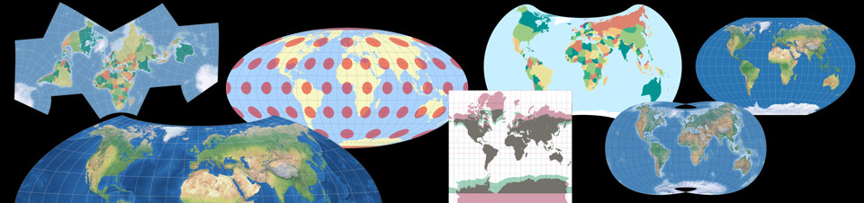
The Results
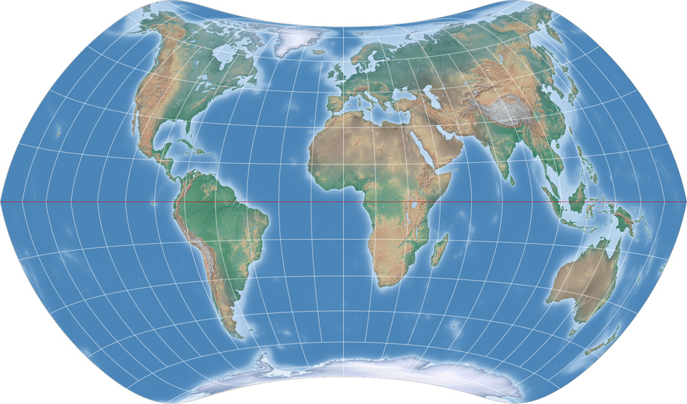
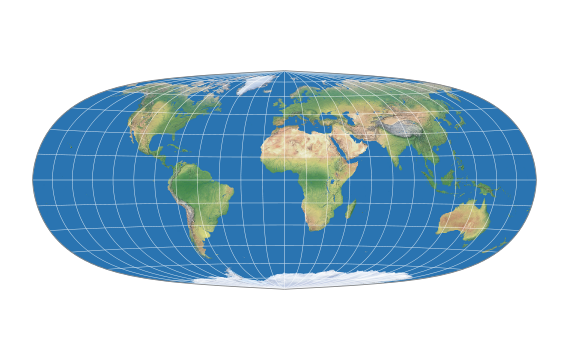
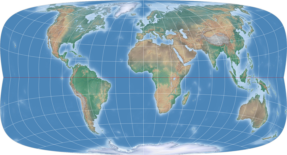
So now, let’s have a look a the complete series. We just had Strebe-Mollweide, but for the sake of completeness, here it is again, along with Strebe-Hammer, Strebe-Kavraiskiy V, Strebe-Sinusoidal, Strebe-Snyder Flat-Pole and Strebe-Snyder Pointed-Pole. All of them rendered with the Bonne φ1 that is assigned to them by default in Geocart:
… And a Personal Preference
And now, yay! I get on my hobby-horse!
Twice before, I’ve experimented with creating a projection that’s either truly equal-area
or at least does not depart too much from equivalence, and
will have a decent shape for Africa as well as for Greenland.
I’m talking about my attempt that I’ve called Wagner-Denoyer and on a certain
configuration of Wagner VII/VIII.
(If you want to know what I mean when I say »decent shape«, read the Wagner-Denoyer article, or be satisfied with the summary that
a decent shape is what looks good in my opinion.)
Now, this goal is easily achieved by various pointed-pole projections, e.g. the
Quartic Authalic or the
Craster’s Parabolic projections, but
I also wanted that the outer meridians don’t bend too much so that e.g. North America
(when the projection is centered to the Greenwich meridian)
isn’t terribly distorted. That again calls for a pole-line projection – but these tend to stretch Greenland horizontally.
Thus, my experiments were using a short pole line, trying to balance out the distortions in a way
that suited my wishes.
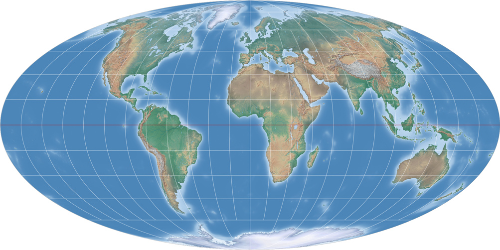
Now, look at Strebe’s series again: Five of them are pointed-pole projections, but – in the configurations shown above –
at least three of them actually look a lot more like pole-line projections, namely
Strebe-Mollweide, Strebe-Kavraiskiy V and Strebe-Snyder Pointed-Pole.
(For the latter two, this property is more pronounced than for the Strebe-Mollweide.)
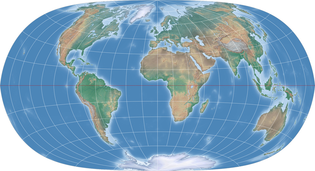
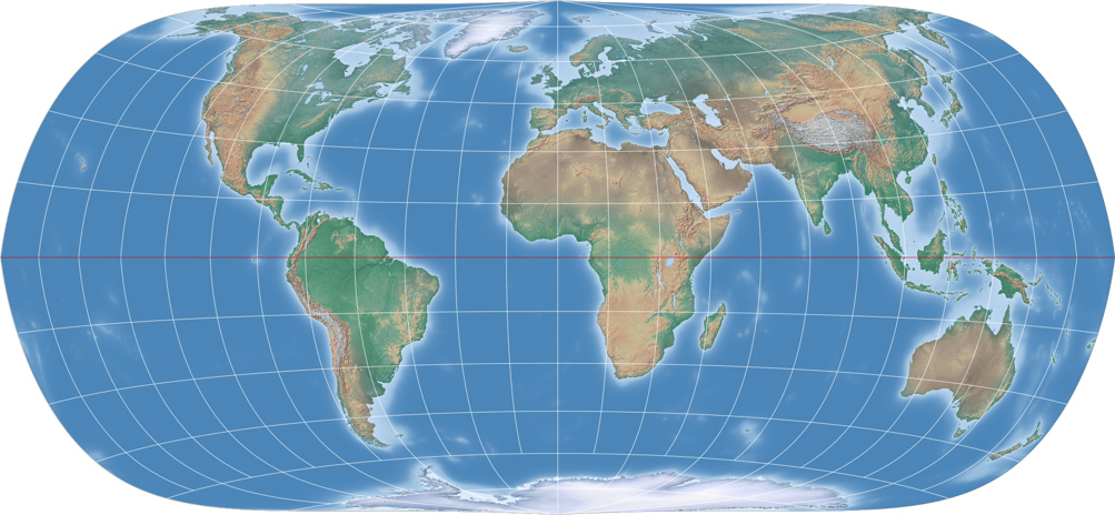
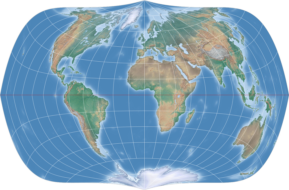
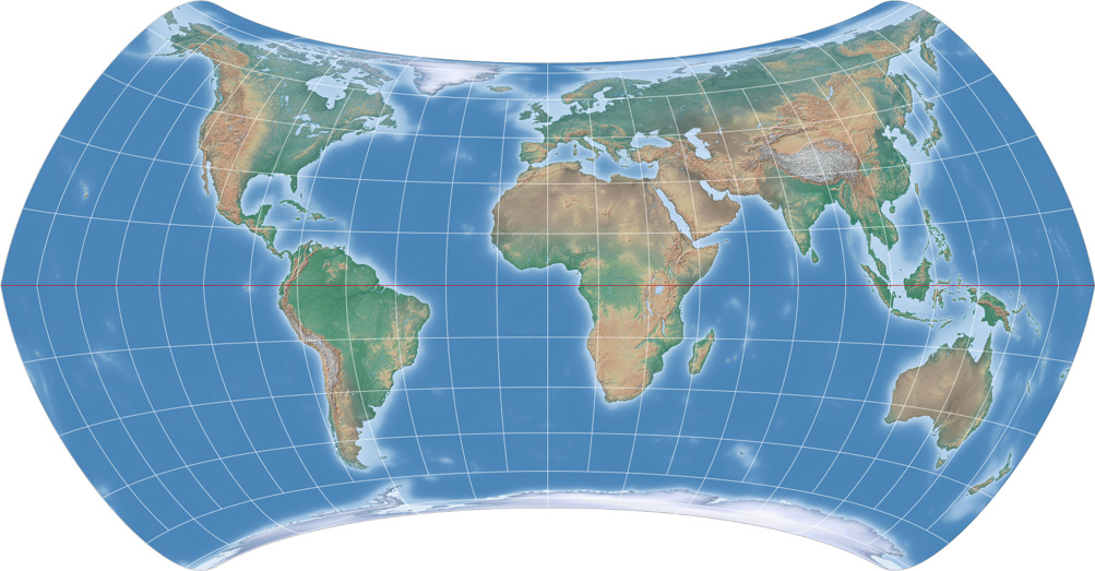
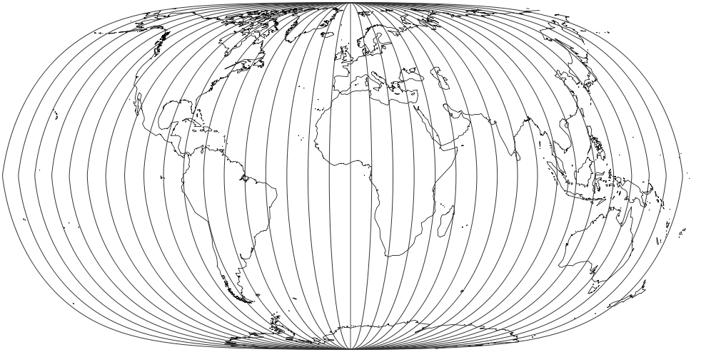
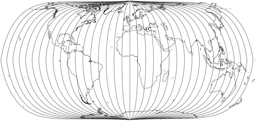
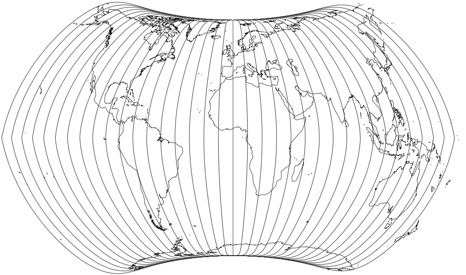
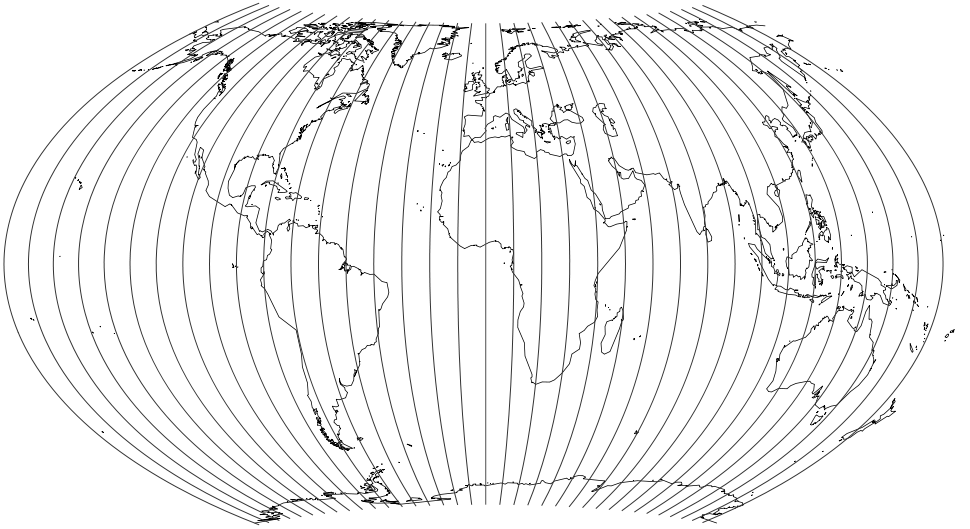
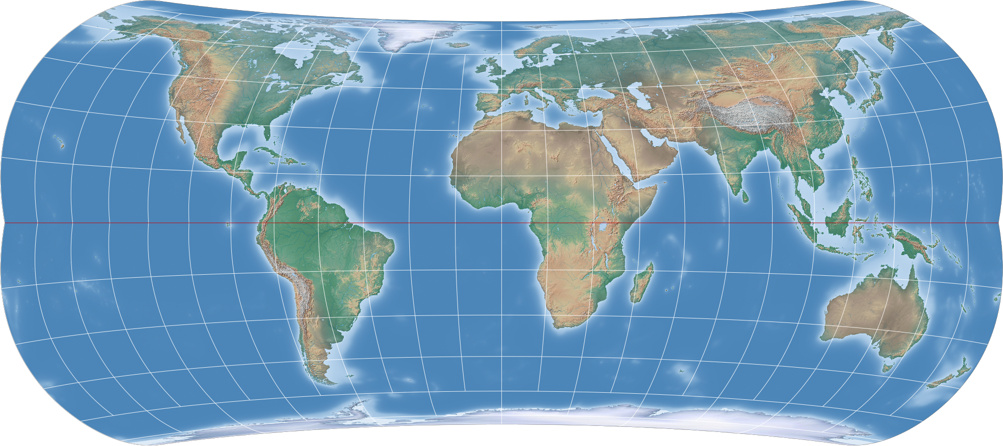
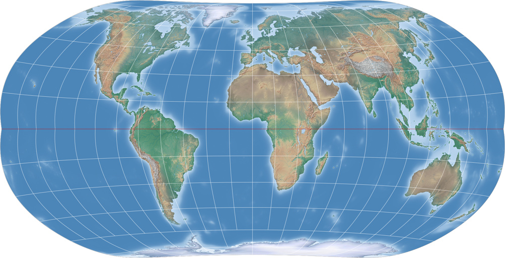
Look at the following images:
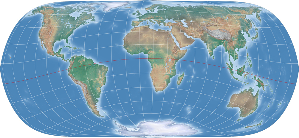
I’ve removed the boundary lines and the parallels, so you can see that the »pole line« (which actually isn’t one)
of the three projections consist only of meridians converging at the poles. In contrast, a real pole-line projection,
the Wagner VII. The difference is quite obvious.
So now you might say: »Ha! In your Wagner-Denoyer article, you clearly state that you wanted a pole-line, so these
projections don’t meet your preferences!«
Well, ummm.
I have to admit: At the time of writing, it simply didn’t occur to me that there might be projections which
seemingly have a pole-line. But now, I have to say: It’s close enough for me. So
Strebe-Mollweide, Strebe-Kavraiskiy V and Strebe-Snyder Pointed-Pole will be added to my personal list
of projections which
are favorable in regards of the goals mentioned above, especially the latter two. Among these two, I can’t quite
decide which one’s my favorite. Both have their own advantages and disadvantages.
Okay.
After handling this personal preference, we’ll continue with things that might interested other people as well. ;-)
A few General Notes
A few observations/remarks regarding Strebe’s projections, randomly listed…
– A peculiar property of all six projections are the kinks of the meridians at the equator, a result of closing the gap as shown above. Strebe himself described them as undesirable, but I really don’t mind them. However they do effect the distribution of distortions (see below).
– When I first saw this projections, I felt that they looked unusual. But meanwhile I’ve changed my mind.
You see, I’m interested in map projections (as are you most likely, since you’re still reading this)
and so I’m used to looking at them, spotting their differences etc.
But let’s be honest, most people are not interested in the matter or don’t even know that something
like map projections exist. To these people, I’ll bet, at least
Strebe-Mollweide, Strebe-Hammer and Strebe-Kavraiskiy V
look perfectly normal, just like a world map has to look – maybe even the two Strebe-Snyder projections as well.
Only Strebe-Sinusoidal has a really striking appearance.
– The circumscribing rectangle of Strebe-Snyder Pointed Pole has an aspect ratio
that is very close to Winkel Tripel’s (original version). So if you’re looking for an equivalent alternative
to Winkel Tripel, here you are.
(Just like the Wagner VII’s circumscribing rectangle is close to Bartholomew’s Winkel Tripel version,
which is not very surprising since Wagner designed it to be an equal-area replacement for the
Winkel Triple.)
– Talking about the Strebe-Snyder Pointed Pole: This projection is not unlike the Strebe 1995 projection, both
in regards of the outer shape and the distribution of distortions.
It almost seems as if Strebe liked the modified Snyder projection a lot, so he tried to create a similar projection
that doesn’t have the flaw of the kinked meridians. Obviously, he succeeded.
It didn’t occur to me before, but the aspect ratio of Strebe 1995 is close
to Winkel Tripel’s, too.
– And something else on the Strebe-Snyder Pointed Pole: I like the variant with Bonne φ1 = 16°N very much. The aspect ratio approaches 1:2, the kinks are relaxed and overall, it’s not dissimilar to Wagner VII (a projection that I like a lot).
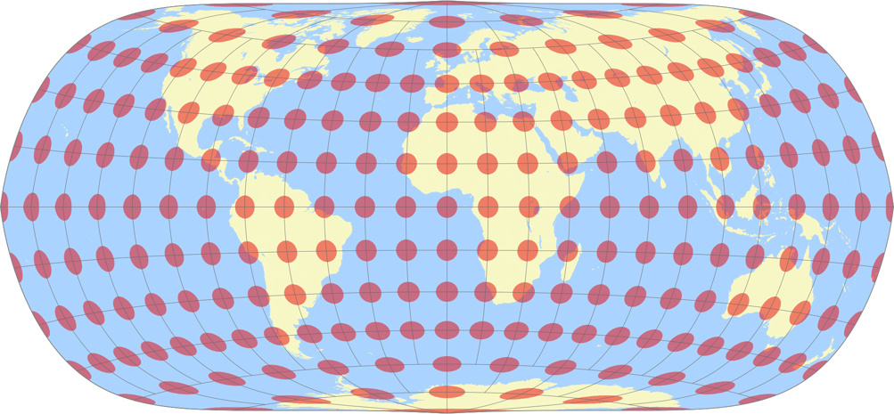
– To show how the latitude of curvature affects the projection, here’s the Strebe-Kavraiskiy V with a Bonne φ1 of 10, 15, 20, 25 and 29 degree North; both in uninterrupted and interrupted form:


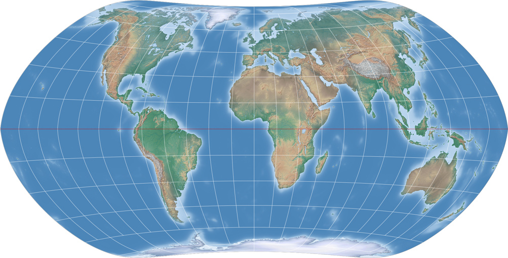
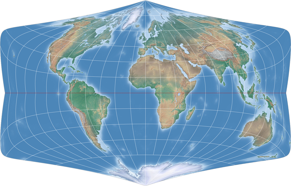
– Another interesting configuration of the Strebe-Kavraiskiy V is shown in the Geocart manual: It’s centered to 11° South und 11° East. While this makes my poor Greenland slide into an area of higher distortion again, the advantage is that this way, all major landmasses including Antarctica are shown without interruptions:
This is of course no special feature of the Strebe-Kavraiskiy V, it can be done with any cylindric, pseudozylindric and lenticular projection as well. But I thought that this might be a good place to show such a configuration…
Something about Rectangles
A lot of people seem to prefer rectangular maps – after all, the paper on which the map will be printed, is rectangular, too, and you don’t want to waste space. But especially for equal-area maps it’s in my opinion very disadvantageous to strive for a rectangular map. In a nutshell, I think the choice of the projection should be determined by what’s inside the boundaries of the map, not the empty space around the map.
A rectangular shape is not very compatible to an equal-area world map. However I do understand the wish not to waste space, so maybe a map that is almost rectangular in shape might be a solution?
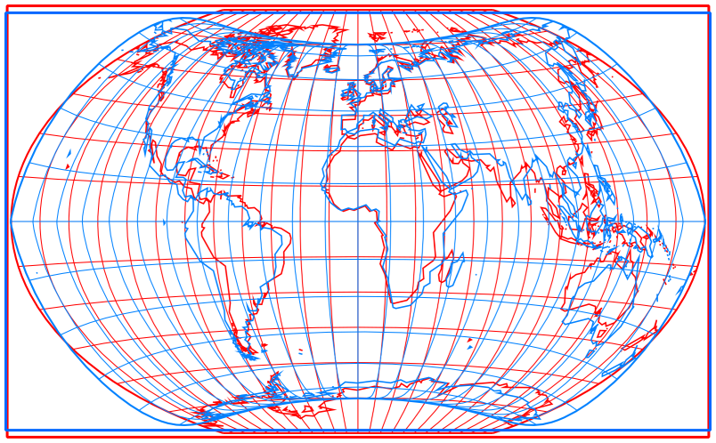
Using Strebe-Kavraiskiy V in the configuration shown above, you’re already quite close: According to my measurements, the map itself uses about 89% of its circumscribing rectangle. Let’s compared it to an equal-area projection that’s really rectangular – the cylindrical Smyth equal-surface (a.k.a. Craster equal-area), which has a similar aspect ratio.
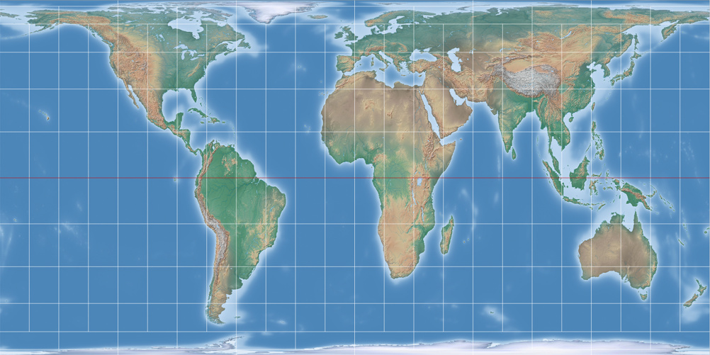
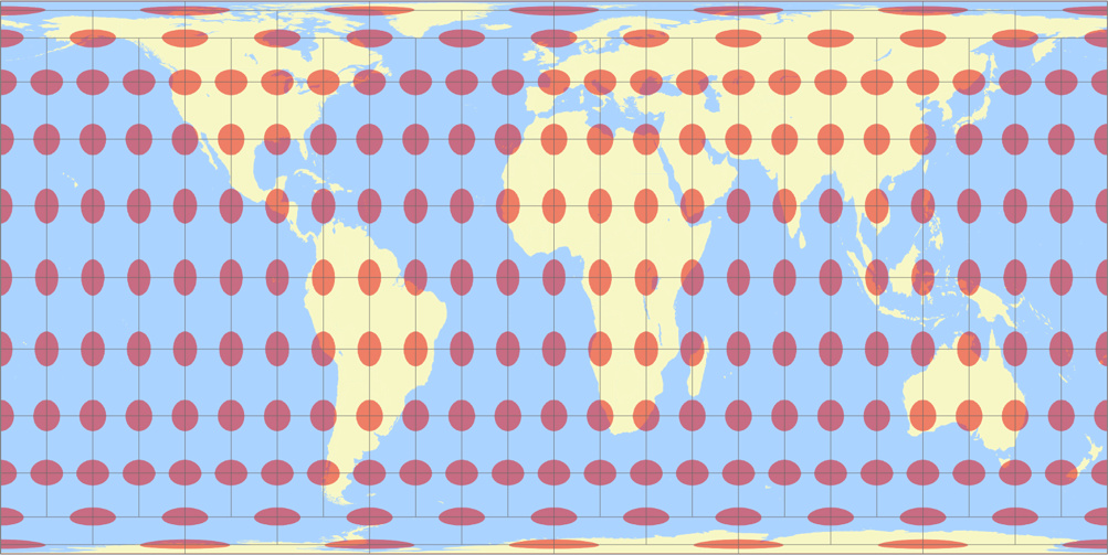
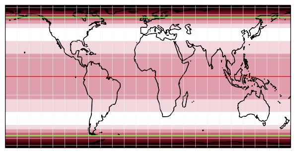
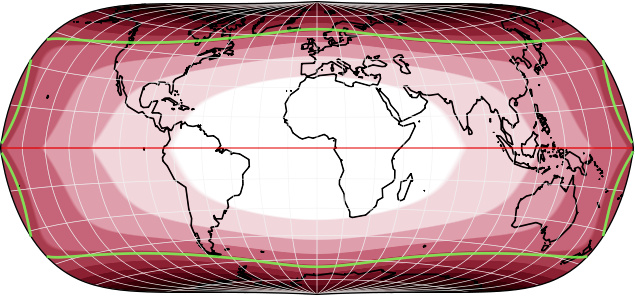
While in the Smyth larger areas of the map are below an angular distortion of 40° (green line), the different distribution of distribution in the Strebe-Kavraiskiy V lead in my opinion to more »natural« shapes of the continents. So if the intended use doesn’t specifically require a rectangular map, I’d happily sacrifice 11% of the space to utilize the better representation.
Of course I’m aware that in many cases, you might prefer a cylindrical projection because of other reasons than to avoid the »waste of space«, e.g. because you like that the graticule consist of straight lines meeting at right angles. However many people who cheered the AuthaGraph world map praised the fact that the map is rectangular, which makes me assume that for some reason, this seems to be very important…
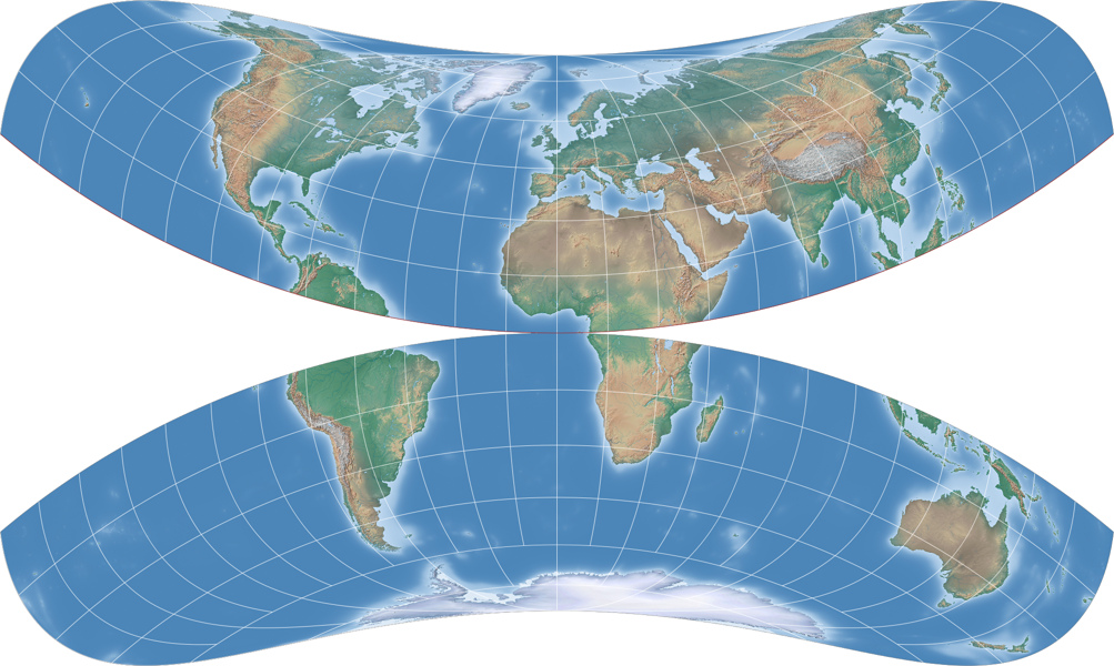
Southern Comfort
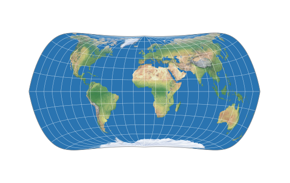
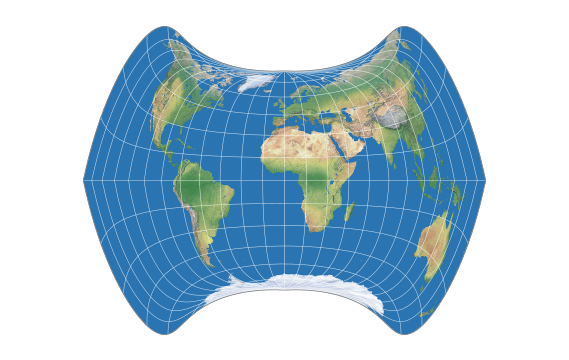
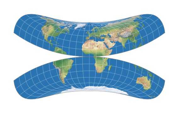
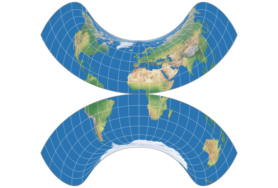
So far, I’ve shown configurations with a Bonne φ1 in the northern hemisphere, but it’s also possible to define a latitude in the southern hemisphere. The results now look unusual indeed, but some of them use even more than 89% of the circumscribing rectangle. Others just look interesting and might be useful if you need a projection that catches the eye.
The kinks of the meridians are, of course, still present, but here, they bend inward which makes the projections look a bit as if the equator was a belt… ;-)
The Strebe-Sinusoidal with Bonne φ1 = 26°S is »diamond-shaped« and probably mainly useful for decorative use. But in this context, here’s a real eye-catcher!
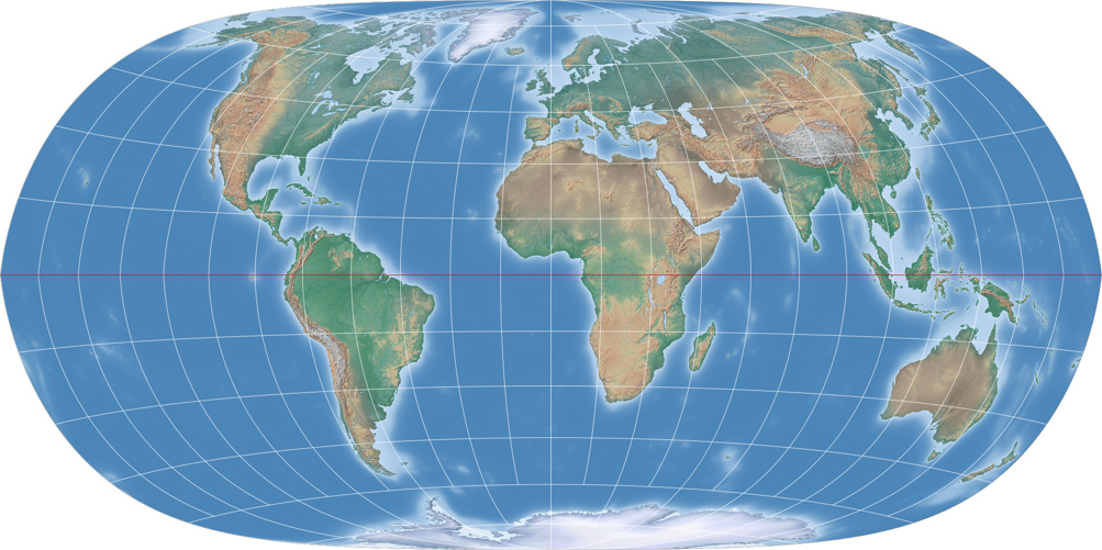
Strebe-Mollweide with Bonne φ1 = 24°S approaches a rectangular shape, which sometimes is desired or useful (see above). While the previous example used about 89% of the total area, we reach about 93% in this case.

And here, the value achieves proud 97%: Strebe-Hammer, Bonne φ1 = 29°S. This configuration has almost the same aspect ratio as Gall-Peters, and again I have to say that in my opinion there is little in favour of the cylindrical projection.
And now, for the last time (I promise!) comparing to a cylindrical projections: Strebe-Snyder Flat Pole with Bonne φ1 = 20°S has an aspect ratio quite close to Behrmann. Okay, I admit, it’s not the greatest projection I’ve ever seen, but I wanted to show a »southern variant« of this projection, too…

Without much ado, my two favorites among the configurations with southern Bonne φ1: It’s the Strebe-Kavraiskiy V again, set to 24°S …
… and the Strebe-Snyder Pointed Pole, 20°S.

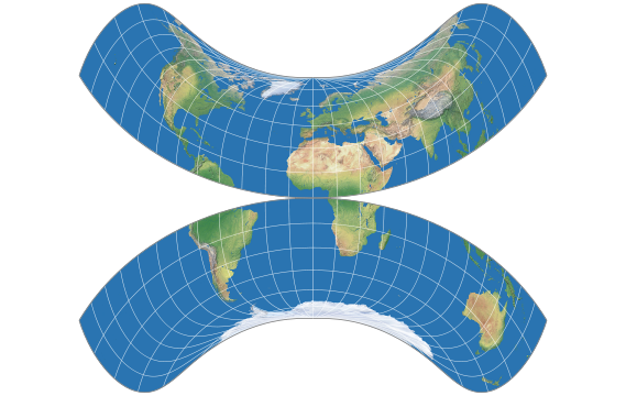
And finally, another specimen of the more unusual type of projections:
Strebe-Snyder Pointed Pole at 35°S.
By the way, there is a projection which is somewhat similar (apart from the kinks), both regarding the outer
shape and the distribution of distortions: I’m talking about Frank Canters’ W30 (or
Low-error equal-area transformation of Hammer-Wagner [Wagner VII] with twofold symmetry
and a correct ratio of the axes), but regrettably I can’t show it here
which is shown in a different blogpost.
If you get your hands on a copy of Canters’ textbook Small-Scale Map Projection Design,
check Figure 5.7 (page 215).
Summary
Strebe’s 1992 series offers six equal-area projections which are customizable and therefore equipped for
a lot of different uses (or personal preferences). The kinked meridians are a certain flaw, but in an
appropriate configuration they don’t stand out very much – or even might be advantageous, if you need
a projection that catches the eye.
Various configurations approach a rectangular shape which sometimes can be advisable.
Of course, you do need the software Geocart to use them which probably is kind of a deal breaker for most people…
References
-
↑
Strebe, Daniel (2018):
A bevy of area-preserving transforms for map projection designers.
available at researchgate.net
 Except where otherwise noted, images on this site are licensed under
Comments
Due to spam posts, comments are now subject to moderation, which means they remain hidden until they are approved by a moderator.
More info
Be the first one to write a comment!